Construction-Vessel
This demo simulates a marine vessel doing crane operations while dynamically positioned. System plants and controllers are modularized according to responsibility and to preserve numerical stability.
FMUs are listed in Table 1.
Table 1: List of FMUs in the Construction Vessel demo.
| FMU name | Description |
|---|---|
| Vessel Model | Simulates the motions of a marine vessel exposed to environmental forces |
| Power Plant | Simulates the vessel’s power plant |
| Thrust Allocation | Maps thrust orders from DP to thruster setpoints |
| Thruster Model | Maps thruster setpoints to forces acting on the vessel |
| Wind Model | Models wind forces acting on the vessel |
| Wave Model | Models first and second order wave forces as disturbances in vessel position |
| Winch | Models the crane and winch |
| DP Controller | DP controller for keeping the vessel at a fixed position |
| Reference Model | Reference model for smoothing the setpoint provided to DP |
System Overview
Thrusters
The simulated vessel has five thrusters: two azimuth thrusters and three tunnel thrusters. Their location with respect to midships is listed in Table 2
Table 2: Thruster Layout
| Thruster | Location w.r.t midships [x, y, z] m |
|---|---|
| Tunnel Thruster 1 | [31, 0, 2.1] |
| Tunnel Thruster 2 | [28.9, 0, 1.9] |
| Tunnel Thruster 3 | [24.75, 0, 1.9] |
| Port Azimuth Thruster | [-36.45, -4, 1.414] |
| Starboard Azimuth Thruster | [-36.45, 4, 1.414] |
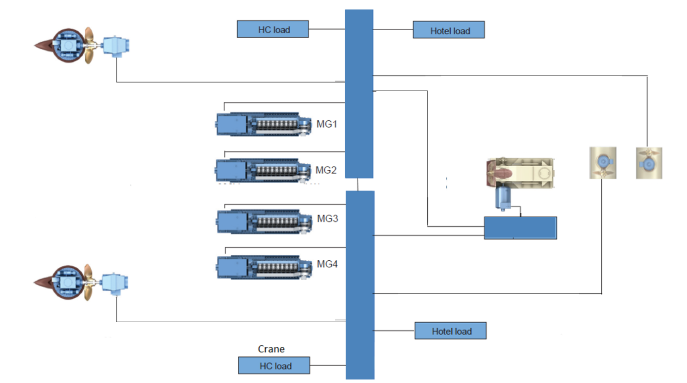
Power Plant
The power plant is responsible for providing power to the thruster, crane and hotel loads. Its topology is shown in Figure 1.
Connections
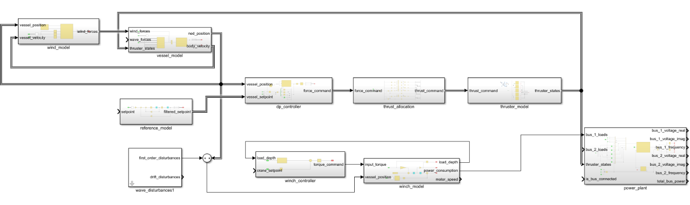
Connections between FMUs are defined using CSE’s internal system structure format. An equivalent simulator topology is shown in the Simulink diagram in Figure 2
FMUS
Every model in the demo is implemented as a Functional Mockup Unit (FMU). FMUs are a common framework for sharing models generated from different tools such as Simulink, SimulationX etc. All FMUs in this demo is compiled for Windows only.
Winch
The winch FMU combines winch dynamics and control. Inside is a PID controller producing torque commands for the winch model with load depth as the control objective. Users interact with the controller by specifying the load depth setpoint.
The winch model calculates load depth by modelling the winch as a second order dynamic system. Vessel position is necessary to adjust load depth for heave motions. The model outputs load depth, motor speed and power consumption for use in the power plant FMU.
Interface descriptions are given in Table 3 and Table 4.
Table 3: Winch model inputs and outputs (I/O).
| Name | I/O | Unit | Description |
|---|---|---|---|
vessel_position.north | I | m | Vessel’s north position in NED frame |
vessel_position.east | I | m | Vessel’s east position in NED frame |
vessel_position.down | I | m | Vessel’s down position in NED frame |
vessel_position.roll | I | rad | Vessel’s roll orientation in NED frame |
vessel_position.pitch | I | rad | Vessel’s pitch orientation in NED frame |
vessel_position.yaw | I | rad | Vessel’s yaw orientation in NED frame |
load_depth_setpoint | I | m | The desired load depth |
load_depth | O | m | Current load depth |
motor_speed | O | rad/s | Current winch motor speed |
power_consumption | O | W | Power consumed |
Table 4: Winch model’s OSP-IS variable groups
| Name | Comprised variables | Description |
|---|---|---|
vessel_position | vessel_position.north, vessel_position.east, vessel_position.down, vessel_position.roll, vessel_position.pitch, vessel_position.yaw | Vessel’s position in NED (North-East-Down) frame |
load_depth | load_depth | Wrapper group for load depth |
motor_speed | motor_speed | Wrapper group for motor speed |
power_consumption | power_consumption | Wrapper group for power consumed |
Reference Model
The reference model produces a smooth setpoint signal based on the desired vessel position. This is achieved by passing the setpoint through a rate limited second order system.
Lists of inputs and outputs are given in Table 5 and Table 6.
Table 5: Reference model inputs and outputs (I/O).
| Name | I/O | Unit | Description |
|---|---|---|---|
setpoint.north | I | m | Desired north position in NED frame |
setpoint.east | I | m | Desired east position in NED frame |
setpoint.yaw | I | rad | Desired yaw orientation in NED frame |
filtered_setpoint.north | O | m | Reference filtered DP setpoint north |
filtered_setpoint.east | O | m | Reference filtered DP setpoint east |
filtered_setpoint.yaw | O | rad | Reference filtered DP setpoint yaw |
Table 6: Reference model’s OSP-IS variable groups
| Name | Comprised variables | Description |
|---|---|---|
vessel_setpoint | vessel_setpoint.north, vessel_setpoint.east, vessel_setpoint.yaw | Vessel position setpoint in NED (North-East-Down) frame |
filtered_vessel_setpoint | filtered_vessel_setpoint.north, filtered_vessel_setpoint.east, filtered_vessel_setpoint.yaw | Reference filtered vessel position setpoint in NED (North-East-Down) frame |
Vessel Model
The vessel model FMU simulates vessel dynamics. Its inputs are environmental forces produced by the wind and wave models and the thruster states from the thruster model. The resultant thrust force is calculated using the thruster layout in Table 2.
The output is the vessel’s velocity expressed in the BODY frame and position expressed in NED.
Lists of inputs and outputs are given in Table 7 and Table 8.
Table 7: Vessel model inputs and outputs (I/O).
| Name | I/O | Unit | Description |
|---|---|---|---|
wave_forces.surge | I | N | Wave force in surge expressed in BODY |
wave_forces.sway | I | N | Wave force in sway expressed in BODY |
wave_forces.heave | I | N | Wave force in heave expressed in BODY |
wave_forces.roll | I | Nm | Wave moment in roll expressed in BODY |
wave_forces.pitch | I | Nm | Wave moment in pitch expressed in BODY |
wave_forces.yaw | I | Nm | Wave moment in yaw expressed in BODY |
wind_forces.surge | I | N | Wind force in surge expressed in BODY |
wind_forces.sway | I | N | Wind force in sway expressed in BODY |
wind_forces.heave | I | N | Wind force in heave expressed in BODY |
wind_forces.roll | I | Nm | Wind moment in roll expressed in BODY |
wind_forces.pitch | I | Nm | Wind moment in pitch expressed in BODY |
wind_forces.yaw | I | Nm | Wind moment in yaw expressed in BODY |
thruster_states.tunnel_thruster_1.power_consumption | I | W | Power consumed by tunnel thruster 1 |
thruster_states.tunnel_thruster_1.thrust | I | N | Thrust produced by tunnel thruster 1 |
thruster_states.tunnel_thruster_2.power_consumption | I | W | Power consumed by tunnel thruster 2 |
thruster_states.tunnel_thruster_2.thrust | I | N | Thrust produced by tunnel thruster 2 |
thruster_states.tunnel_thruster_3.power_consumption | I | W | Power consumed by tunnel thruster 3 |
thruster_states.tunnel_thruster_3.thrust | I | N | Thrust produced by tunnel thruster 3 |
thruster_states.main_propeller_port.power_consumption | I | W | Power consumed by port azimuth thruster |
thruster_states.main_propeller_port.thrust | I | N | Thrust produced by port azimuth thruster |
thruster_states.main_propeller_port.azimuth | I | deg | Azimuth of port azimuth thruster |
thruster_states.main_propeller_starboard.power_consumption | I | W | Power consumed by starboard azimuth thruster |
thruster_states.main_propeller_starboard.thrust | I | N | Thrust produced by starboard azimuth thruster |
thruster_states.main_propeller_starboard.azimuth | I | deg | Azimuth of starboard azimuth thruster |
body_velocity.surge | O | m/s | Vessel’s surge velocity expressed in BODY |
body_velocity.sway | O | m/s | Vessel’s sway velocity expressed in BODY |
body_velocity.heave | O | m/s | Vessel’s heave velocity expressed in BODY |
body_velocity.roll | O | rad/s | Vessel’s roll velocity expressed in BODY |
body_velocity.pitch | O | rad/s | Vessel’s pitch velocity expressed in BODY |
body_velocity.yaw | O | rad/s | Vessel’s yaw velocity expressed in BODY |
ned_position.north | O | m | Vessel’s north position expressed in NED |
ned_position.east | O | m | Vessel’s east position expressed in NED |
ned_position.down | O | m | Vessel’s down position expressed in NED |
ned_position.roll | O | rad | Vessel’s roll orientation expressed in NED |
ned_position.pitch | O | rad | Vessel’s pitch orientation expressed in NED |
ned_position.yaw | O | rad | Vessel’s yaw orientation expressed in NED |
Table 8: Vessel model’s OSP-IS variable groups
| Name | Comprised variables | Description |
|---|---|---|
wind_forces | wind_forces.surge, wind_forces.sway, wind_forces.heave, wind_forces.roll, wind_forces.pitch wind_forces.yaw | Wind forces acting on vessel in BODY frame |
wave_forces | wave_forces.surge, wave_forces.sway, wave_forces.heave, wave_forces.roll, wave_forces.pitch wave_forces.yaw | Wave forces acting on vessel in BODY frame |
tunnel_thruster_1 | thruster_states.tunnel_thruster_1.power_consumption, thruster_states.tunnel_thruster_1.thrust | Input group for tunnel thruster 1 |
tunnel_thruster_2 | thruster_states.tunnel_thruster_2.power_consumption, thruster_states.tunnel_thruster_2.thrust | Input group for tunnel thruster 2 |
tunnel_thruster_3 | thruster_states.tunnel_thruster_3.power_consumption, thruster_states.tunnel_thruster_3.thrust | Input group for tunnel thruster 3 |
main_propeller_port | thruster_states.main_propeller_port.power_consumption, thruster_states.main_propeller_port.thrust, thruster_states.main_propeller_port.azimuth | Input group for tunnel main propeller port |
main_propeller_starboard | thruster_states.main_propeller_starboard.power_consumption, thruster_states.main_propeller_starboard.thrust, thruster_states.main_propeller_starboard.azimuth | Input group for tunnel main propeller starboard |
ned_position | ned_position.north, ned_position.east, ned_position.down, ned_position.roll, ned_position.pitch ned_position.yaw | Vessel position in NED |
body_velocity | body_velocity.surge, body_velocity.sway, body_velocity.heave, body_velocity.roll, body_velocity.pitch body_velocity.yaw | Vessel velocity in BODY |
Thrust Allocation
The thrust allocation FMU transforms the force commands from DP to thruster setpoints. The setpoints are passed to the thruster model which calculates the resultant force.
Lists of inputs and outputs are given in Table 9 and Table 10.
Table 9: Thrust allocation inputs and outputs (I/O).
| Name | I/O | Unit | Description |
|---|---|---|---|
force_command.surge | I | N | Desired force in surge expressed in BODY |
force_command.sway | I | N | Desired force in sway expressed in BODY |
force_command.yaw | I | Nm | Desired moment in yaw expressed in BODY |
thrust_command.main_propeller_port.azimuth | O | deg | Azimuth command to port azimuth thruster |
thrust_command.main_propeller_port.rpm | O | [ 0…1 ] | RPM command to port azimuth thruster |
thrust_command.main_propeller_starboard.azimuth | O | deg | Azimuth command to starboard azimuth thruster |
thrust_command.main_propeller_starboard.rpm | O | [ 0…1 ] | RPM command to starboard azimuth thruster |
thrust_command.tunnel_thruster_1.rpm | O | [ 0…1 ] | RPM command to tunnel thruster 1 |
thrust_command.tunnel_thruster_2.rpm | O | [ 0…1 ] | RPM command to tunnel thruster 2 |
thrust_command.tunnel_thruster_3.rpm | O | [ 0…1 ] | RPM command to tunnel thruster 3 |
Table 10: Thrust Allocation’s OSP-IS variable groups
| Name | Comprised variables | Description |
|---|---|---|
force_command | force_command.surge, force_command.sway, force_command.yaw | Force command from DP |
tunnel_thruster_1_command | thrust_command.tunnel_thruster_1.rpm. | Command to tunnel thruster 1 |
tunnel_thruster_2_command | thrust_command.tunnel_thruster_2.rpm. | Command to tunnel thruster 2 |
tunnel_thruster_3_command | thrust_command.tunnel_thruster_3.rpm. | Command to tunnel thruster 3 |
main_propeller_port_command | thrust_command.main_propeller_port.rpm., thrust_command.main_propeller_port.azimuth. | Command to main propeller port |
main_propeller_starboard_command | thrust_command.main_propeller_starboard.rpm., thrust_command.main_propeller_starboard.azimuth. | Command to main propeller starboard |
Thruster Model
The thruster model simulates thruster dynamics using setpoints produced by the thrust allocator. The output is a thruster state structure consisting of power consumption, thrust and, for azimuth thrusters, azimuth angle.
Lists of inputs and outputs are given in Table 11 and Table 12.
Table 11: Thruster model inputs and outputs (I/O).
| Name | I/O | Unit | Description |
|---|---|---|---|
thrust_command.main_propeller_port.azimuth | I | deg | Azimuth command to port azimuth thruster |
thrust_command.main_propeller_port.rpm | I | [ 0…1 ] | RPM command to port azimuth thruster |
thrust_command.main_propeller_starboard.azimuth | I | deg | Azimuth command to starboard azimuth thruster |
thrust_command.main_propeller_starboard.rpm | I | [ 0…1 ] | RPM command to starboard azimuth thruster |
thrust_command.tunnel_thruster_1.rpm | I | [ 0…1 ] | RPM command to tunnel thruster 1 |
thrust_command.tunnel_thruster_2.rpm | I | [ 0…1 ] | RPM command to tunnel thruster 2 |
thrust_command.tunnel_thruster_3.rpm | I | [ 0…1 ] | RPM command to tunnel thruster 3 |
thruster_states.tunnel_thruster_1.power_consumption | O | W | Power consumed by tunnel thruster 1 |
thruster_states.tunnel_thruster_1.thrust | O | N | Thrust produced by tunnel thruster 1 |
thruster_states.tunnel_thruster_2.power_consumption | O | W | Power consumed by tunnel thruster 2 |
thruster_states.tunnel_thruster_2.thrust | O | N | Thrust produced by tunnel thruster 2 |
thruster_states.tunnel_thruster_3.power_consumption | O | W | Power consumed by tunnel thruster 3 |
thruster_states.tunnel_thruster_3.thrust | O | N | Thrust produced by tunnel thruster 3 |
thruster_states.main_propeller_port.power_consumption | O | W | Power consumed by port azimuth thruster |
thruster_states.main_propeller_port.azimuth | O | deg | Azimuth of port azimuth thruster |
thruster_states.main_propeller_port.thrust | O | N | Thrust produced by port azimuth thruster |
thruster_states.main_propeller_starboard.power_consumption | O | W | Power consumed by starboard azimuth thruster |
thruster_states.main_propeller_starboard.azimuth | O | deg | Azimuth of starboard azimuth thruster |
thruster_states.main_propeller_starboard.thrust | O | N | Thrust produced by starboard azimuth thruster |
Table 12: Thruster Model’s OSP-IS variable groups
| Name | Comprised variables | Description |
|---|---|---|
tunnel_thruster_1_command | thrust_command.tunnel_thruster_1.rpm. | Command to tunnel thruster 1 |
tunnel_thruster_2_command | thrust_command.tunnel_thruster_2.rpm. | Command to tunnel thruster 2 |
tunnel_thruster_3_command | thrust_command.tunnel_thruster_3.rpm. | Command to tunnel thruster 3 |
main_propeller_port_command | thrust_command.main_propeller_port.rpm., thrust_command.main_propeller_port.azimuth. | Command to main propeller port |
main_propeller_starboard_command | thrust_command.main_propeller_starboard.rpm., thrust_command.main_propeller_starboard.azimuth. | Command to main propeller starboard |
tunnel_thruster_1_state | thrust_command.tunnel_thruster_1.power_consumed, thrust_command.tunnel_thruster_1.rpm | Tunnel thruster 1 state |
tunnel_thruster_2_state | thrust_command.tunnel_thruster_2.power_consumed, thrust_command.tunnel_thruster_2.rpm | Tunnel thruster 2 state |
tunnel_thruster_3_state | thrust_command.tunnel_thruster_3.power_consumed, thrust_command.tunnel_thruster_3.rpm | Tunnel thruster 3 state |
main_propeller_port_state | thruster_states.main_propeller_port.power_consumption, thruster_states.main_propeller_port.thrust, thruster_states.main_propeller_port.azimuth | Main propeller port state |
main_propeller_starboard_state | thruster_states.main_propeller_starboard.power_consumption, thruster_states.main_propeller_starboard.thrust, thruster_states.main_propeller_starboard.azimuth | Main propeller starboard |
DP Controller
The DP controller FMU calculates the forces necessary to keep the vessel at a desired position. The position setpoint is provided by the reference model and the current position by the vessel model. The forces calculated by DP is used as input the thrust allocation FMU. The control algorithm is simple and consists only of a PID controller for each degree of freedom.
Lists of inputs and outputs are given in Table 13 and Table 14.
Table 13: DP controller inputs and outputs (I/O).
| Name | I/O | Unit | Description |
|---|---|---|---|
vessel_position.north | I | m | Vessel’s north position in NED frame |
vessel_position.east | I | m | Vessel’s east position in NED frame |
vessel_position.down | I | m | Vessel’s down position in NED frame |
vessel_position.roll | I | rad | Vessel’s roll orientation in NED frame |
vessel_position.pitch | I | rad | Vessel’s pitch orientation in NED frame |
vessel_position.yaw | I | rad | Vessel’s yaw orientation in NED frame |
vessel_setpoint.north | I | m | Desired north position in NED |
vessel_setpoint.east | I | m | Desired east position in NED |
vessel_setpoint.yaw | I | rad | Desired yaw orientation in NED |
force_command.surge | O | N | Desired force in surge expressed in BODY |
force_command.sway | O | N | Desired force in sway expressed in BODY |
force_command.yaw | O | Nm | Desired moment in yaw expressed in BODY |
Table 14: DP controllers’s OSP-IS variable groups
| Name | Comprised variables | Description |
|---|---|---|
ned_position | vessel_position.north, vessel_position.east, vessel_position.down, vessel_position.roll, vessel_position.pitch, vessel_position.yaw | Vessel position in NED |
vessel_setpoint | vessel_setpoint.north, vessel_setpoint.east, vessel_setpoint.yaw | Vessel setpoint in NED |
force_command | force_command.surge, force_command.sway, force_command.yaw | Force command from DP |
Wind Model
The wind model is responsible for modelling external wind forces acting on the vessel.
Lists of inputs and outputs are given Table 15 and Table 16.
Table 15: Wind model inputs and outputs (I/O).
| Name | I/O | Unit | Description |
|---|---|---|---|
vessel_position.north | I | m | Vessel’s north position in NED frame |
vessel_position.east | I | m | Vessel’s east position in NED frame |
vessel_position.down | I | m | Vessel’s down position in NED frame |
vessel_position.roll | I | rad | Vessel’s roll orientation in NED frame |
vessel_position.pitch | I | rad | Vessel’s pitch orientation in NED frame |
vessel_position.yaw | I | rad | Vessel’s yaw orientation in NED frame |
vessel_velocity.surge | I | m/s | Vessel’s surge velocity in BODY |
vessel_velocity.sway | I | m/s | Vessel’s sway velocity in BODY |
vessel_velocity.heave | I | m/s | Vessel’s heave velocity in BODY |
vessel_velocity.roll | I | rad/s | Vessel’s roll velocity in BODY |
vessel_velocity.pitch | I | rad/s | Vessel’s pitch velocity in BODY |
vessel_velocity.yaw | I | rad/s | Vessel’s yaw velocity in BODY |
wind_forces.surge | O | N | Wind force in surge expressed in BODY |
wind_forces.sway | O | N | Wind force in sway expressed in BODY |
wind_forces.heave | O | N | Wind force in heave expressed in BODY |
wind_forces.roll | O | Nm | Wind moment in roll expressed in BODY |
wind_forces.pitch | O | Nm | Wind moment in pitch expressed in BODY |
wind_forces.yaw | O | Nm | Wind moment in yaw expressed in BODY |
Table 16: Wind model’s OSP-IS variable groups
| Name | Comprised variables | Description |
|---|---|---|
ned_position | vessel_position.north, vessel_position.east, vessel_position.down, vessel_position.roll, vessel_position.pitch, vessel_position.yaw | Vessel position in NED |
vessel_velocity | vessel_velocity.surge, vessel_velocity.sway, vessel_velocity.heave, vessel_velocity.roll, vessel_velocity.pitch, vessel_velocity.yaw | Vessel velocity in BODY |
wind_forces | wind_forces.surge, wind_forces.sway, wind_forces.heave, wind_forces.roll, wind_forces.pitch wind_forces.yaw | Wind forces acting on vessel in BODY frame |
Wave Model
The wave model simulates first and second order wave forces acting on the vessel. The model is implemented as a linearized wave spectrum producing position disturbances. Meaning that wave disturbances are added directly to the vessel position calculated by the vessel model FMU.
A complete list of outputs is given in Table 17. ‘ The sea state and response magnitude can be tuned by changing the parameters listed in Table 18.
Table 17: Wave model inputs and outputs (I/O).
| Name | I/O | Unit | Description |
|---|---|---|---|
first_order_disturbances.north | O | m | First order wave disturbances north |
first_order_disturbances.east | O | m | First order wave disturbances east |
first_order_disturbances.down | O | m | First order wave disturbances down |
first_order_disturbances.roll | O | rad | First order wave disturbances roll |
first_order_disturbances.pitch | O | rad | First order wave disturbances pitch |
first_order_disturbances.yaw | O | rad | First order wave disturbances yaw |
drift_disturbances.north | O | m | Wave drift north |
drift_disturbances.east | O | m | Wave drift east |
drift_disturbances.down | O | m | Wave drift down |
drift_disturbances.roll | O | rad | Wave drift roll |
drift_disturbances.pitch | O | rad | Wave drift pitch |
drift_disturbances.yaw | O | rad | Wave drift yaw |
Table 18: Wave model parameters
| Name | Unit | Description |
|---|---|---|
wave_height | m | Significant wave height of sea state |
peak_frequency | rad/s | Peak frequency of sea state |
k_north | - | Tuning constant for first order wave disturbances north |
k_east | - | Tuning constant for first order wave disturbances east |
k_down | - | Tuning constant for first order wave disturbances down |
k_roll | - | Tuning constant for first order wave disturbances roll |
k_pitch | - | Tuning constant for first order wave disturbances pitch |
k_yaw | - | Tuning constant for first order wave disturbances yaw |
north_drift_limit | m | Max wave drift north |
east_drift_limit | m | Max wave drift east |
yaw_drift_limit | rad | Max wave drift yaw |
Power System
The power system simulates the power plant shown in Figure 4. There is no feedback from the plant to the thruster and the crane. Meaning that both act as if they have unlimited available power. However, power consumption is fed to the power system which calculates bus frequency, voltage and produced power
List of inputs and outputs is given in Table 19 and Table 20.
Table 19: Wave model inputs and outputs (I/O).
| Name | I/O | Unit | Description |
|---|---|---|---|
bus_1_loads.active_power | I | W | Active power of external load connected to bus 1 |
bus_1_loads.reactive_power | I | Var | Reactive power of external load connected to bus 1 |
bus_2_loads.active_power | I | W | Active power of external load connected to bus 2 |
bus_2_loads.reactive_power | I | Var | Reactive power of external load connected to bus 2 |
is_bus_connected | I | - | Bus 1 and bus 2 are connected if true |
thruster_states.tunnel_thruster_1.power_consumption | I | W | Power consumed by tunnel thruster 1 |
thruster_states.tunnel_thruster_1.thrust | I | N | Thrust produced by tunnel thruster 1 |
thruster_states.tunnel_thruster_2.power_consumption | I | W | Power consumed by tunnel thruster 2 |
thruster_states.tunnel_thruster_2.thrust | I | N | Thrust produced by tunnel thruster 2 |
thruster_states.tunnel_thruster_3.power_consumption | I | W | Power consumed by tunnel thruster 3 |
thruster_states.tunnel_thruster_3.thrust | I | N | Thrust produced by tunnel thruster 3 |
thruster_states.main_propeller_port.power_consumption | I | W | Power consumed by port azimuth thruster |
thruster_states.main_propeller_port.azimuth | I | deg | Azimuth of port azimuth thruster |
thruster_states.main_propeller_port.thrust | I | N | Thrust produced by port azimuth thruster |
thruster_states.main_propeller_starboard.power_consumption | I | W | Power consumed by starboard azimuth thruster |
thruster_states.main_propeller_starboard.azimuth | I | deg | Azimuth of starboard azimuth thruster |
thruster_states.main_propeller_starboard.thrust | I | N | Thrust produced by starboard azimuth thruster |
bus_1_frequency | O | rad/s | Frequency of bus 1 |
bus_1_voltage_imag | O | V | Imaginary part of bus 1 voltage |
bus_1_voltage_real | O | V | Real part of bus 1 voltage |
bus_2_frequency | O | rad/s | Frequency of bus 2 |
bus_2_voltage_imag | O | V | Imaginary part of bus 2 voltage |
bus_2_voltage_real | O | V | Real part of bus 2 voltage |
bus_power[1,1] | O | W | Power produced on bus 1 |
bus_power[1,2] | O | W | Power produced on bus 2 |
Table 20: Power System’s OSP-IS variable groups
| Name | Comprised variables | Description |
|---|---|---|
bus_1_loads | bus_1_loads.active_power, bus_1_load.reactive_power | Power loads on bus 1 |
bus_2_loads | bus_2_loads.active_power, bus_2_load.reactive_power | Power loads on bus 2 |
winch_power | bus_1_loads.active_power | Power consumed by the winch |
tunnel_thruster_1_state | thrust_command.tunnel_thruster_1.power_consumed, thrust_command.tunnel_thruster_1.rpm | Tunnel thruster 1 state |
tunnel_thruster_2_state | thrust_command.tunnel_thruster_2.power_consumed, thrust_command.tunnel_thruster_2.rpm | Tunnel thruster 2 state |
tunnel_thruster_3_state | thrust_command.tunnel_thruster_3.power_consumed, thrust_command.tunnel_thruster_3.rpm | Tunnel thruster 3 state |
main_propeller_port_state | thruster_states.main_propeller_port.power_consumption, thruster_states.main_propeller_port.thrust, thruster_states.main_propeller_port.azimuth | Main propeller port state |
main_propeller_starboard_state | thruster_states.main_propeller_starboard.power_consumption, thruster_states.main_propeller_starboard.thrust, thruster_states.main_propeller_starboard.azimuth | Main propeller starboard |