Quarter-Truck
System Description
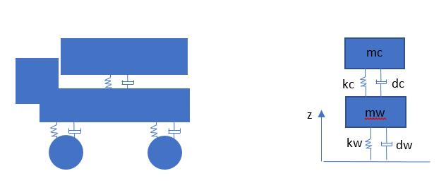
This example describes a low-level test case for the performance of libcosim in terms of accuracy and efficiency [1]. Figure 1 shows a simplified model of a quarter truck with two masses mWheel and mChassis representing the mass of wheel and chassis respectively. Both masses have a single vertical degree of freedom coupled by a linear spring-damper system representing the suspension force and tire force. The ground profile is given as external input.
Model Description
For co-simulation, three FMUs are generated namely the chassis, wheel and ground. The ground and chassis each have one variable group for connecting to the wheel which has two variable groups that are commutative to those of the ground and chassis. Table 1 shows the connections for these variables. Specifically for this example, the first element in the variable name indicates which fmu it belongs to. The local default parameters used in the model are listed in Table 2.
Table 1: Input and output variables of the quarter truck fmus for connection
| Output | Input | Description |
|---|---|---|
chassis.p.e | wheel.p.e | Vertical force from the chassis suspension applied to the wheel |
wheel.p.f | chassis.p.f | Vertical velocity of the wheel sent to the chassis part |
wheel.p.e | ground.p.e | Vertical force from the truck wheel tyres applied to the ground |
ground.p.f | wheel.p.f | Ground profile, given as the vertical velocity variation sent to the truck wheel |
Table 2: Local parameters of the quarter truck model
| Parameter | Default Value | Description |
|---|---|---|
mWheel | 40 kg | Wheel Mass |
mChassis | 400 kg | Chassis Mass |
kWheel | 150000 Nm^-1 | Wheel Spring Stiffness |
dWheel | 0 Nsm^-1 | Wheel Damper Coefficient |
kChassis | 15000 Nm^-1 | Chassis Spring Stiffness |
dChassis | 1000 Nsm^-1 | Chassis Damper Coefficient |
Simulation Results
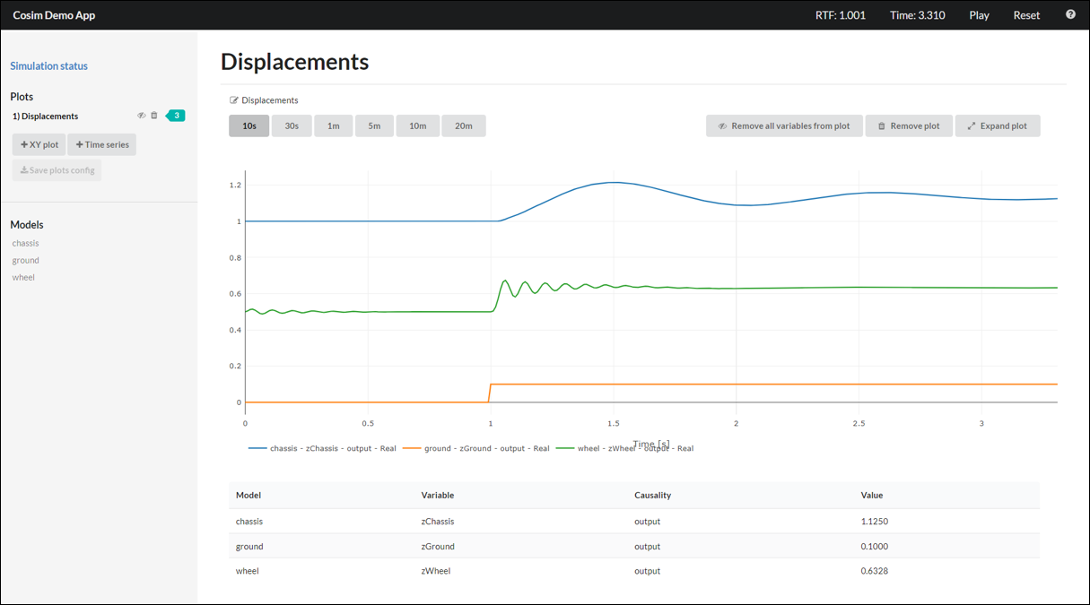
The following scenario is performed as example: The system starts from equilibrium state where zWheel = zChassis = 0. The ground profile is defined as a step function excited by a jump of 0.1m in vertical direction at 1s. Figure 2 below shows the simulation results using the cosim demo app. In the plot the vertical displacements of the wheel and the chassis are displayed.
More information on how to use the cosim demo app is available in the user guide, where the DP-Ship demo test case was used as an example.
References
[1] Arnold, M., Clauss, C., & Schierz, T. (2014). Error analysis and error estimates for co-simulation in FMI for model exchange and co-simulation V2. 0. In Progress in Differential-Algebraic Equations (pp. 107-125). Springer, Berlin, Heidelberg.