Gunnerus Path-following
This document describes the Functional Mock-up Units (FMUs) necessary to run the simulation case of a vessel following waypoints (WPs) using line-of-sight (LOS) guidance principle.
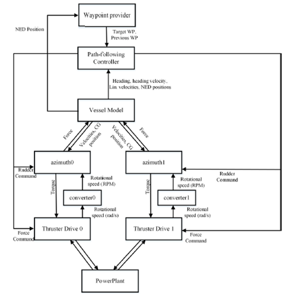
System Description
Each component/FMU of the simulation case will be described in the following sections. Only relevant variables will be described for each FMU. The names of the simulation objects are given in the table below. For additional information about the individual FMUs and their variables, unpack the FMU and open the modelDescription.xml file
Table 1: List of FMUs in the Gunnerus Path-following system.
| FMU name | Description |
|---|---|
| TrajectoryController | Controls the speed and heading angle to make vessel follow path.. |
| WaypointProvider2DOF | Issues waypoints (target and previous) to controller. |
| Converter | A simple unit conversion |
| ThrusterDrive | Thruster drive calculates the rmp of the thruster given the desired thrust command (propulsion force) [1] |
| PMAzimuth | Main propuslion azimuth thruster |
| PowerPlant | Provides power to the thruster drive [2] |
| VesselFmu | 6DOF hull model including the environment model |
Trajectory Controller
This FMU holds the controller functionality required in order to converge to a certain desired vessel speed and heading angle. The latter is calculated by the LOS guidance scheme and the aggressiveness may be altered by changing the input variable “lookaheadDistance” > 0. Otherwise, the convergence properties of the speed and heading angle to desired values are controlled by the ProportionalIntegral-Derivative (PID) regulator parameters.
Table 2: Trajectory Controller inputs and outputs (I/O).
| Name | I/O | Description |
|---|---|---|
enable | I | Boolean variable. Outputs updated rudder/force commands only if true. |
autopilot.heading.kp | I | Proportional gain for heading regulator |
autopilot.heading.ki | I | Integral gain for heading regulator |
autopilot.heading.kd | I | Derivative gain for heading regulator |
autopilot.speed.kp | I | Proportional gain for speed regulator |
autopilot.speed.ki | I | Integral gain for speed regulator |
autopilot.speed.kd | I | Derivative gain for speed regulator |
northPosition | I | North position of vessel [m] |
eastPosition | I | East position of vessel [m] |
surgeVelocity | I | Velocity of vessel in surge direction [m/s] |
swayVelocity | I | Velocity of vessel in sway direction [m/s] |
headingAngle | I | Heading angle of vessel [deg] |
targetWP.north | I | North position of the target WP |
targetWP.east | I | East position of the target WP |
prevWP.north | I | North position of the previous WP |
prevWP.east | I | East position of the previous WP |
forceCommand | O | The force command requested from each of the two main thrusters [N] |
rudderCommand | O | The azimuth angle of the two main thrusters [deg] |
Waypoint Provider
This FMU holds the positions (North/East) of the WPs. The TrajectoryController.fmu receives a target WP and a previous WP and tries to converge to the straight line between the two WP in the direction of the target WP. When the horizontal plane distance between the vessel and the target WP is less than the numerical value of the variable “wpSwitchDistance”, the next WP in the list is assigned to the target WP and the previous target WP is assigned to the previous WP.
Table 3: Waypoint Provider inputs and outputs (I/O).
| Name | I/O | Description |
|---|---|---|
northPosition | I | North position of vessel [m] |
eastPosition | I | East position of vessel [m] |
headingAngle | I | Heading angle of vessel [deg |
mode | I | If mode = 1, the fmu accepts additional wps input at runtime to a list. If mode != 1, the fmu uses a list specified at initialization. Either a hardcoded list (packman shape) or a user-specified list will be used based on the numerical value of wp1. If wp1 is initialized to a value not equal to 0.0, the user-specified list is used. |
wpSwitchDistance | I | The horizontal plane distance, between the target WP and the vessel, at which the WP list is incremented. Threshold for accepting a target WP as “reached”. |
Converter
This is a simple unit converter created to convert between radians per second, issued by ThrusterDrive.fmu -> Shaft.f, and Revolutions Per Minute (RPM), received by PMAzimuth.fmu -> input_act_revs.
Table 4: Converter inputs and outputs (I/O).
| Name | I/O | Description |
|---|---|---|
input.radPerSec | I | Input frequency in radians per second |
output.rpm | O | Output frequency in revolutions per minute |
Thruster Drive
Table 5: Thruster Drive inputs and outputs (I/O).
| Name | I/O | Description |
|---|---|---|
d_in.e | I | |
q_in.e | I | |
ThrustCom | I | |
Shaft.e | I | |
d_in.f | O | |
q_in.f | O | |
Shaft.f | O |
PM Azimuth
Table 5: PM Azimuth inputs and outputs (I/O).
| Name | I/O | Description |
|---|---|---|
input_enabled | I | |
input_is_main_propulsion | I | |
input_x_rel_ap | I | |
input_y_rel_cl | I | |
input_z_rel_bl | I | |
input_prop_diam | I | |
input_t | I | |
input_distancetohull | I | |
input_bilgeradius | I | |
input_rho | I | |
input_act_revs | I | |
input_act_angle | I | |
input_cg_x_rel_ap | I | |
input_cg_y_rel_cl | I | |
input_cg_z_rel_bl | I | |
input_cg_surge_vel | I | |
input_cg_sway_vel | I | |
input_yaw_vel | I | |
input_lpp | I | |
output_force_heave | O | |
output_force_surg | O | |
output_force_sway | O | |
output_x_rel_ap | O | |
output_y_rel_cl | O | |
output_z_rel_bl | O |
VesselFMU
Holds the vessel model and models applying environmental forces onto the vessel.
Table 6: VesselFMU and outputs (I/O).
| Name | I/O | Description |
|---|---|---|
vesselZipFile | I | Absolute path of vessel model zip archive |
global_cur_dir | I | The direction of ocean current (0 is towards North) [deg] |
global_cur_vel | I | The ocean current velocity [m/s] |
input_global_wind_dir | I | The wind direction (0 is from North) [deg] |
input_global_wind_vel | I | The wind velocity [m/s] |
additionalBodyForce[0] | I | Magnitude (Newtons) of surge/sway/heave force produced by the port azimuth thruster and the point of attack of the force on the hull relative to AP/BL/CL. |
additionalBodyForce[1] | I | Magnitude (Newtons) of surge/sway/heave force produced by the port azimuth thruster and the point of attack of the force on the hull relative to AP/BL/CL. |
cgShipMotion.ned.north | O | North position of vessel (1st element of the “NED positions” vector in below figure) |
cgShipMotion.ned.east | O | East position of vessel (2nd element of the “NED positions” vector in below figure) |
cgShipMotion.angularDisplacement.yaw | O | Yaw angle of the vessel relative to north direction given in the below figure as the “heading” variable |
cgShipMotion.angularVelocity.yaw | O | The angular velocity of the vessel about the yaw axis (deg/s) |
cgShipMotion.linearVelocity | O | Components of the vessel velocity along the surge, sway and heave axes (m/s) |
cg_x_rel_ap, cg_y_rel_cl, cg_z_rel_bl | O | Location of the center of gravity (CG) of the vessel relative to AP/BL/CL |
References
[1] S. Skjong, M. Rindarøy, L. T. Kyllingstad, V. Æsøy, and E. Pedersen, “Virtual prototyping of maritime systems and operations: applications of distributed co-simulations,” J. Mar. Sci. Technol., pp. 1–19, 2017.
[2] S. Skjong and E. Pedersen, “A real-time simulator framework for marine power plants with weak power grids,” Mechatronics, vol. 47, pp. 24–36, Nov. 2017.