Launch and Recovery System
System Description
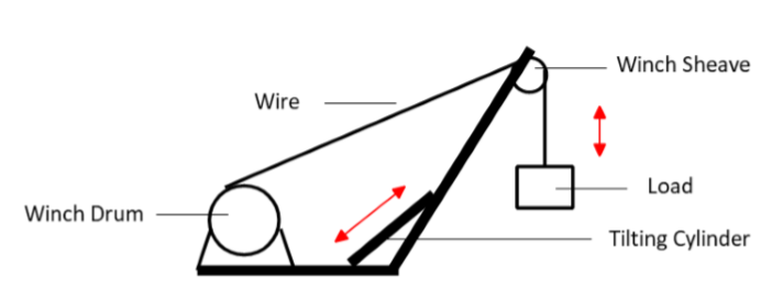
The launch and recovery system (LARS) consist of two main subsystems, i.e., the A-Frame and the winch, as shown in Figure 1. Figure 2 depicts the modeling sketch of the LARS. The LARS model of interest has two degrees of freedom (DoF) enabled by the tilting cylinder and the winch drum through the sheave connected to the A-Frame beam.
Subsystems, Submodels and FMUS
The reference system model is divided into eight sub-models and FMUs as shown in Figure 3
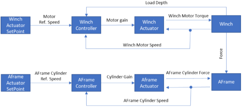
Table 1: List of FMUs in the LARS system.
| FMU name | Input | Output | Default Parameters |
|---|---|---|---|
| WinchActuatorSetpoint | winchSetpoint | ||
| WinchController | winchSetpoint, loadSpeed | motorGain | Proportional gain K = 10. Derivative time constant Td = 0.1. Derivative gain limitation N = 10. Integral time constant Ti = 0.1. loadDepth_min max/init length 1m/1000m,/200m |
| WinchActuator | motorGain, motorSpeed | motorTorque | Max motor output torque T = 10kNm |
| Winch | motorTorque1, motorTorque2, motorTorque3 | motorSpeed, loadSpeed, winchForce | Gear ratio r = 141 Gear efficiency e = 0.925 Drum inertia i = 1600kgm^2 Drum diameter d = 1.36m Drum width B = 1.1m Max wire length wireLmax = 1000m Load mass m = 500kg Wire diameter D= 0.02m Wire Young’s Modulus E = 85e9 Wire damping critical coefficient c= 0.5 Total friction coefficient r = 1 |
| AFrameActuatorSetpoint | aFrameSetpoint | ||
| AFrameController | aFrameSetpoint, cylinderSpeed | cylinderGain | Proportional gain K = 2 Derivative time constant Td = 0.01 Derivative gain limitation N = 10 Integral time constant Ti = 0.01 Cylinder min/max/init length 1.2/1.7/1.7m |
| AFrameActuator | cylinderGain, cylinderSpeed | cylinderForce | Max cylinder output force F = 5000kN |
| AFrame | cylinderForce, winchForce | cylinderSpeed | tilting leg length l=2m cylinder positions a = 0.46m, b = 1.3572m |
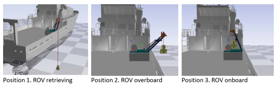
Default Scenario Setup
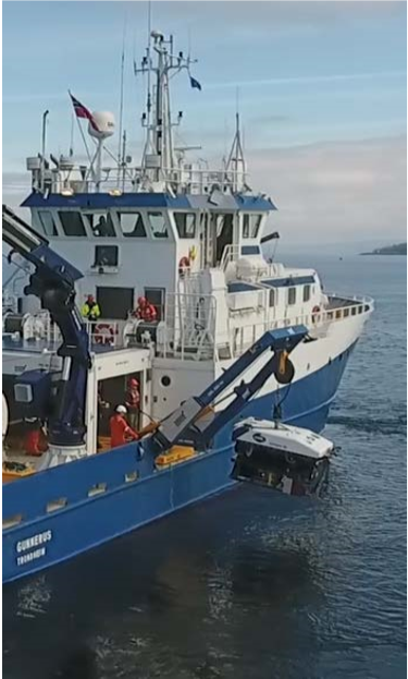
The simulated scenario presents the retrieving of the ROV, as shown in Figure 4. Specifically, From 5s to 95s, retrieving the ROV by spooling in the winch drum. From 95s to 100s, by retracing the tilting cylinder the A-Frame operates from overboard position to the onboard position.
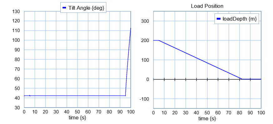
Simulation Results
Given the default setpoint values in WinchActuatorSetpoint and AFrameActuatorSetpoint , the tilting angle of the A-Frame and the position of the load are shown in Figure 5. Time step 0.001s.