Gunnerus-DP
The purpose of this demo case is to demonstrate separation of control systems and simulators in libcosim and the use of network FMUs.
This toplogy is common when performing hardware-in-the-loop (HIL) simulations. In a HIL setup, the control system is deployed on production hardware and hooked up to an external simulator. The external simulator can be deployed to whatever hardware is available as long as it enables an interface compatible with the control system. The same toplogy can also be seen when running software-in-the-loop (SIL) simulations. SIL is typically used to test and verify system functionality and it is not a requirement that the control system is deployed to production hardware.
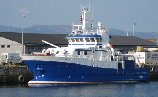
This demo case demonstrates that doing simulations with this kind of topology is feasible using libcosim and the OSP configuration format. The case simulates a DP controlled vessel performing a box maneuver while exposed to external forces. NTNU’s research vessel, Gunnerus (Figure 1), has been used as reference for both the vessel and control plant.
System Description
The HIL/SIL toplogy is emulated by splitting the simulation into two instances: one running the control system (Figure 2) and another running the simulator models (Figure 3). Each instance can run separately on different hardware. A single system configuration (Figure 4), where the control plant and simulator is executed in the same instance, is also provided.
The control system and simulator communicates using a network FMU, custom made for this demo. Each system instantiates a version with an interface for receiving and sending states. For instance, the network FMU in the control system sends thruster commands and receives vessel and environment states. The single system configuration does not use the network FMU.
A list of all FMUs is given in Table 1.
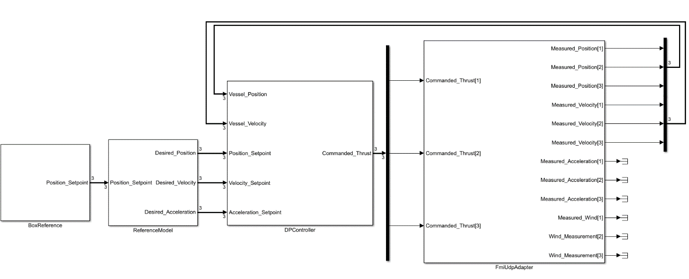
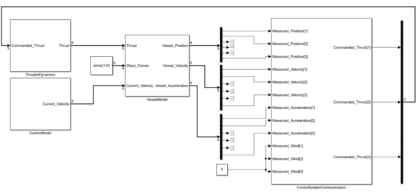
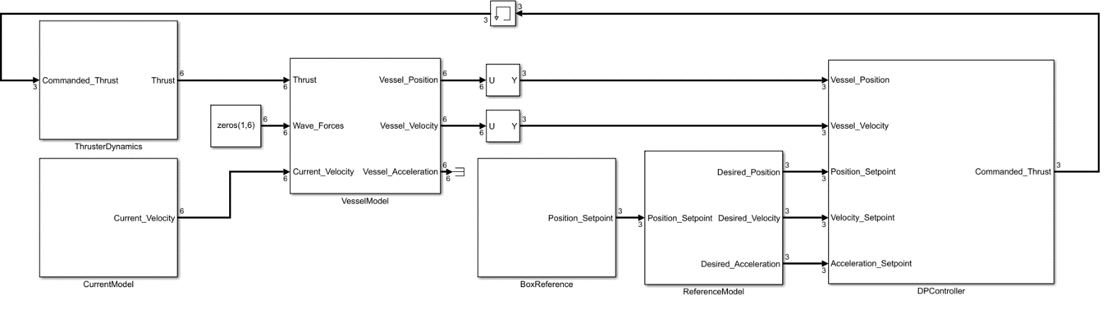
Table 1: List of FMUs in the Gunnerus-DP case.
| FMU name | Description |
|---|---|
| Box Reference | Provides setpoints for a box maneuver |
| Control System Communication | Network FMU handling communication between control system and simulator |
| Current Model | Current model generating surface current velocities |
| DP Controller | 3-Dof DP controller |
| Reference Model | Reference model providing setpoints to DP |
| Simulator Communication | Network FMU handling communication between control system and simulator. Shown in Figure 2 as FmiUdpAdapter. |
| Thruster Dynamics | Thruster dynamics |
| Vessel Model | 6-dof vessel model |
Note that all these fmus contain binaries for win64 only.
OSP Interface Specification
This demo case uses the OSP interface specification (OSP-IS) to simplify model connections. OSP-IS makes it possible to organize FMU variables, defined in a modelDescription.xml file, into higher level variable groups. This removes the tedious work of connecting individual FMU variables and enables configurators to operate at a higher abstraction level.
FMU Descriptions
Box Reference Model
The box reference FMU generates setpoints for north, east and yaw. The model is shown in Figure 5 and the output in Figure 6. The result is a box maneuver which takes the vessel between 0-40m north and 0-40m east. The setpoints are not intended to be directly sent to the DP controller, but should be passed through a reference filter first.
The FMU’s variables are described in Table 2 and OSP-is variable groups in Table 3.
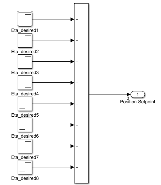
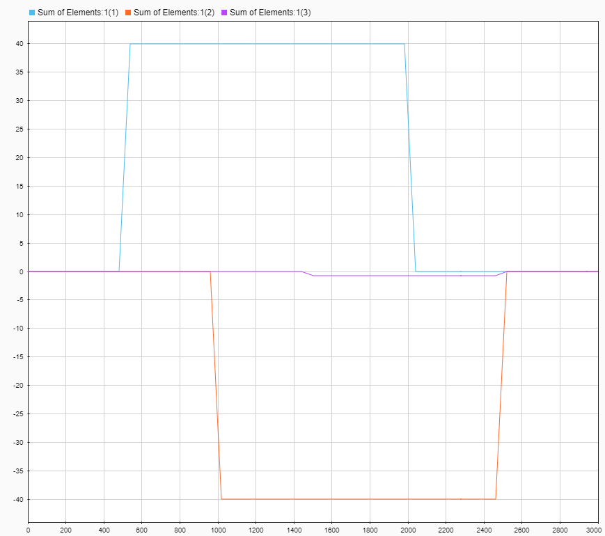
Table 2: Box Reference model inputs and outputs (I/O).
| Name | I/O | Unit | Description |
|---|---|---|---|
Position[1] | O | m | Setpoint North |
Position[2] | O | m | Setpoint East |
Position[3] | O | rad | Setpoint Yaw |
Table 3: Box Reference model’s OSP-IS variable groups.
| Name | Comprised variables | Description |
|---|---|---|
position_setpoint | Position[1], Position[2], Position[3] | Setpoint in NED (North-East-Down) |
Control System Communication
The control system communication FMU is instantiated in the simulator and is responsible for transmitting simulated states to the control system and to receive thruster commands from the DP controller. Its interface and OSP-IS variables are described in Table 4 and Table 5.
Table 4: Control System Communication inputs and outputs (I/O).
| Name | I/O | Unit | Description |
|---|---|---|---|
Measured_Position[1] | I | m | Vessel north position |
Measured_Position[2] | I | m | Vessel east position |
Measured_Position[3] | I | rad | Vessel yaw position |
Measured_Velocity[1] | I | m/s | Vessel surge velocity |
Measured_Velocity[2] | I | m/s | Vessel sway velocity |
Measured_Velocity[3] | I | rad/s | Vessel yaw velocity |
Measured_Wind[1] | I | m/s | Wind velocity in surge |
Measured_Wind[2] | I | m/s | Wind velocity in sway |
Measured_Wind[3] | I | rad/s | Wind velocity in yaw |
Commanded_Thrust[1] | O | N | Desired thrust from DP in surge |
Commanded_Thrust[2] | O | N | Desired thrust from DP in sway |
Commanded_Thrust[3] | O | Nm | Desired thrust from DP in yaw |
Table 5: Control System Communication’s OSP-IS variable groups.
| Name | Comprised variables | Description |
|---|---|---|
position_3dof | Measured_Position[1], Measured_Position[2], Measured_Position[3] | NED vector |
velocity_3dof | Measured_Velocity[1], Measured_Velocity[2], Measured_Velocity[3] | 3D body velocity vector |
acceleration_3dof | Measured_Acceleration[1], Measured_Acceleration[2], Measured_Acceleration[3] | 3D body acceleration vector |
wind_measurements | Measured_Wind[1], Measured_Wind[2], Measured_Wind[3] | Wind velocity vector |
thrust_command | Commanded_Thrust[1], Commanded_Thrust[2], Commanded_Thrust[3] | Thrust command in surge, sway and yaw from control system |
Current Model
The current model FMU simulates 2D surface current that is used by the vessel model to calculate drag and resistance. It can be enabled or disabled by setting a parameter on the FMU.
The model is based on the Simulink diagram shown in Figure 8 and its FMU and OSP-IS interface is described in Table 6, Table 7 and Table 8. The current velocity vector has six entries, however, only the x and y componentents are non-zero.
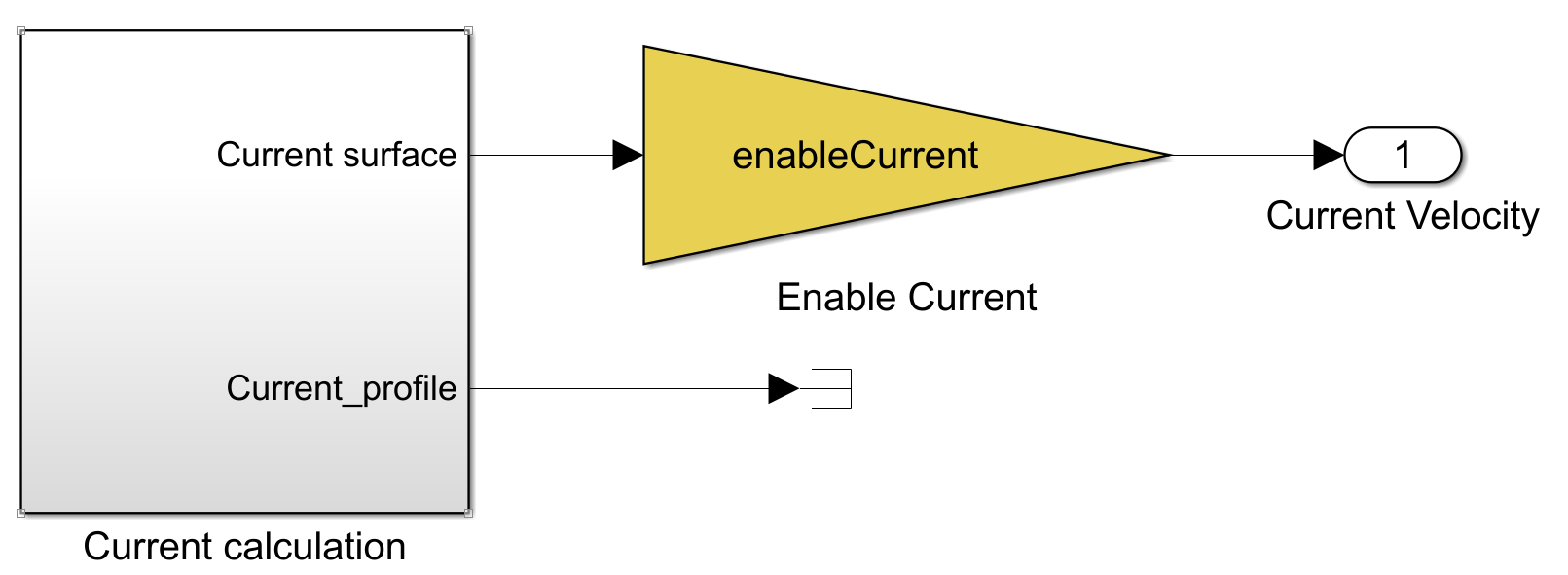
Table 6: Current Model inputs and outputs (I/O).
| Name | I/O | Unit | Description |
|---|---|---|---|
Current_Velocity[1] | O | m/s | Current velocity in surge |
Current_Velocity[2] | O | m/s | Current velocity in sway |
Current_Velocity[3] | O | m/s | Always zero |
Current_Velocity[4] | O | rad/s | Always zero |
Current_Velocity[5] | O | rad/s | Always zero |
Current_Velocity[6] | O | rad/s | Always zero |
Table 7: Current Model Parameters.
| Name | Default | Description |
|---|---|---|
Enable_Current | True | Enables or disables current |
Table 8: Current Model’s OSP-IS variable groups.
| Name | Comprised variables | Description |
|---|---|---|
current_velocity | Current_Velocity[1], Current_Velocity[2], Current_Velocity[3], Current_Velocity[4], Current_Velocity[5], Current_Velocity[6] | Current velocity vector |
DP Controller
This FMU implements Gunnerus’ DP control system. The control plant consists of proportional-derivative, integrator and reference feed forward parts, all of which can be independently enabled or disabled.
The controller inputs are the vessel’s position in NED (North-East-Down), velocity in BODY, position setpoint in NED, velocity setpoint in BODY and acceleration setpoint in BODY. The acceleration setpoint is required if the reference feed-forward part of the model is enabled.
A complete list of inputs, outputs, tunables and OSP.IS variable groups are shown in Table 9, Table 10 and Table 11.
Table 9: DP Controller inputs and outputs (I/O).
| Name | I/O | Unit | Description |
|---|---|---|---|
Vessel_Position[1] | I | m | Vessel north position |
Vessel_Position[2] | I | m | Vessel east position |
Vessel_Position[3] | I | rad | Vessel yaw orientation |
Vessel_Velocity[1] | I | m/s | Vessel surge velocity |
Vessel_Velocity[2] | I | m/s | Vessel sway velocity |
Vessel_Velocity[3] | I | rad/s | Vessel yaw velocity |
Position_Setpoint[1] | I | m | Position setpoint north |
Position_Setpoint[2] | I | m | Position setpoint east |
Position_Setpoint[3] | I | rad | Orientation setpoint yaw |
Velocity_Setpoint[1] | I | m/s | Velocity setpoint surge |
Velocity_Setpoint[2] | I | m/s | Velocity setpoint sway |
Velocity_Setpoint[3] | I | rad/s | Velocity setpoint yaw |
Acceleration_Setpoint[1] | I | m/s^2 | Acceleration setpoint surge |
Acceleration_Setpoint[2] | I | m/s^2 | Acceleration setpoint sway |
Acceleration_Setpoint[3] | I | rad/s^2 | Acceleration setpoint yaw |
Commanded_Thrust[1] | O | N | Thrust command in surge |
Commanded_Thrust[2] | O | N | Thrust command in sway |
Commanded_Thrust[3] | O | Nm | Thrust command in yaw |
Table 10: DP Controller Parameters
| Name | Default | Description |
|---|---|---|
EnablePDControl | True | Enables or disables proportional derivative control |
EnableIAction | True | Enables or disables integral action |
EnableRefFF | True | Enables or disables reference feed forward |
Table 11: DP Controllers’s OSP-IS variable groups.
| Name | Comprised variables | Description |
|---|---|---|
position_3dof | Measured_Position[1], Measured_Position[2], Measured_Position[3] | NED vector from vessel model |
velocity_3dof | Measured_Velocity[1], Measured_Velocity[2], Measured_Velocity[3] | 3D body velocity vector from vessel model |
position_setpoint | Position_Setpoint[1], Position_Setpoint[2], Position_Setpoint[3] | NED position setpoint |
velocity_setpoint | Velocity_Setpoint[1], Velocity_Setpoint[2], Velocity_Setpoint[3] | BODY velocity setpoint |
acceleration_setpoint | Acceleration_Setpoint[1], Acceleration_Setpoint[2], Acceleration_Setpoint[3] | BODY velocity setpoint |
thrust_command | Commanded_Thrust[1], Commanded_Thrust[2], Commanded_Thrust[3] | Thrust command in surge, sway and yaw from control system |
Reference Model
The reference model provides smooth setpoint signals for the DP controller, ensuring a controlled and stable operation. The signals are based on the desired position provided by the box reference FMU.
A simulink representation of the model is shown in Figure 8 and its inputs, outputs and OSP-IS variable groups are described in Table 12 and Table 13.
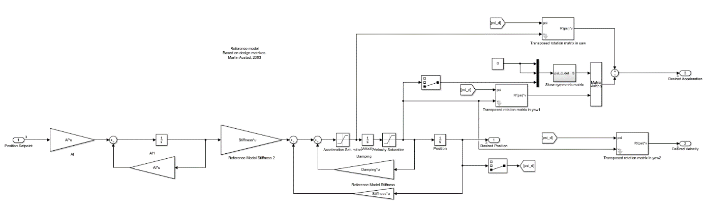
Table 12: Reference Model inputs and outputs (I/O).
| Name | I/O | Unit | Description |
|---|---|---|---|
Position_Setpoint[1] | I | m | User defined setpoint north |
Position_Setpoint[2] | I | m | User defined setpoint east |
Position_Setpoint[3] | I | rad | User defined setpoint yaw |
Desired_Position[1] | O | m | Position setpoint north to DP |
Desired_Position[2] | O | m | Position setpoint east to DP |
Desired_Position[3] | O | rad | Orientation setpoint yaw to DP |
Desired_Velocity[1] | O | m/s | Velocity setpoint surge to DP |
Desired_Velocity[2] | O | m/s | Velocity setpoint sway to DP |
Desired_Velocity[3] | O | rad/s | Velocity setpoint yaw to DP |
Desired_Acceleration[1] | O | m/s^2 | Acceleration setpoint surge to DP |
Desired_Acceleration[2] | O | m/s^2 | Acceleration setpoint sway to DP |
Desired_Acceleration[3] | O | rad/s^2 | Acceleration setpoint yaw to DP |
Table 13: Reference Model’s OSP-IS variable groups.
| Name | Comprised variables | Description |
|---|---|---|
position_setpoint | Position_Setpoint[1], Position_Setpoint[2], Position_Setpoint[3] | NED position setpoint |
desired_position | Desired_Position[1], Desired_Position[2], Desired_Position[3] | Reference filtered NED position setpoint |
desired_velocity | Desired_Velocity[1], Desired_Velocity[2], Desired_Velocity[3] | Reference filtered BODY velocity setpoint |
desired_acceleration | Desired_Acceleration[1], Desired_Acceleration[2], Desired_Acceleration[3] | Reference filtered BODY velocity setpoint |
Simulator Communication
The simulator communication FMU is instantiated in the control system and is responsible for transmitting commands to the control system and to receive simulated states vessel and environment models. Its FMU and OSP-IS interfaces are described in Table 14 and Table 15.
Table 14: Simulator Communication inputs and outputs (I/O).
| Name | I/O | Unit | Description |
|---|---|---|---|
Commanded_Thrust[1] | I | N | User defined setpoint north |
Commanded_Thrust[2] | I | N | User defined setpoint east |
Commanded_Thrust[3] | I | Nm | User defined setpoint yaw |
Measured_Position[1] | O | m | Position setpoint north to DP |
Measured_Position[2] | O | m | Position setpoint east to DP |
Measured_Position[3] | O | rad | Orientation setpoint yaw to DP |
Measured_Velocity[1] | O | m/s | Velocity setpoint surge to DP |
Measured_Velocity[2] | O | m/s | Velocity setpoint sway to DP |
Measured_Velocity[3] | O | rad/s | Velocity setpoint yaw to DP |
Measured_Acceleration[1] | O | m/s^2 | Acceleration setpoint surge to DP |
Measured_Acceleration[2] | O | m/s^2 | Acceleration setpoint sway to DP |
Measured_Acceleration[3] | O | rad/s^2 | Acceleration setpoint yaw to DP |
Measured_Wind[1] | O | m/s | Wind velocity in surge |
Measured_Wind[2] | O | m/s | Wind velocity in sway |
Measured_Wind[3] | O | rad/s | Wind velocity in yaw |
Table 15: Simulator Communication’s OSP-IS variable groups.
| Name | Comprised variables | Description |
|---|---|---|
thrust_command | Commanded_Thrust[1], Commanded_Thrust[2], Commanded_Thrust[3] | Thrust command from DP |
position_3dof | Measured_Position[1], Measured_Position[2], Measured_Position[3] | NED vector from vessel model |
velocity_3dof | Measured_Velocity[1], Measured_Velocity[2], Measured_Velocity[3] | 3D body velocity vector from vessel model |
acceleration_3dof | Measured_Acceleration[1], Measured_Acceleration[2], Measured_Acceleration[3] | 3D body acceleration vector |
wind_measurements | Measured_Wind[1], Measured_Wind[2], Measured_Wind[3] | Wind velocity vector |
Thruster Dynamics
This FMU implements simplified thruster dynamics as a low pass filter which can be enabled or disabled. The thruster command is mapped directly to forces acting on the vessel without considering thruster placement. This mapping is instantaneous if thruster dynamics are disabled. It is also possible to enable or disable thrust saturation.
The FMU is based on the simulink model shown in Figure 9 and its interfaces are described in Table 16, Table 17 and Table 18.
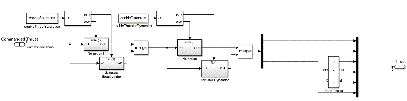
Table 16: Thruster Dynamics inputs and outputs (I/O).
| Name | I/O | Unit | Description |
|---|---|---|---|
Commanded_Thrust[1] | I | N | Thrust demand from DP in surge |
Commanded_Thrust[2] | I | N | Thrust demand from DP in sway |
Commanded_Thrust[3] | I | Nm | Thrust demand from DP in yaw |
Thrust[1] | O | N | Thrust force in surge |
Thrust[2] | O | N | Thrust force in sway |
Thrust[3] | O | N | Thrust force in heave (always zero) |
Thrust[4] | O | Nm | Thrust moment in roll (always zero) |
Thrust[5] | O | Nm | Thrust moment in pitch (always zero) |
Thrust[6] | O | Nm | Thrust moment in yaw |
Table 17: Thruster Dynamics Parameters
| Name | Default | Description |
|---|---|---|
EnableThrustSaturation | True | Enables or disable thrust force saturation |
EnableThrusterDynamics | True | Enables or disables thruster dynamcis |
Table 18: Simulator Communication’s OSP-IS variable groups.
| Name | Comprised variables | Description |
|---|---|---|
thrust_command | Commanded_Thrust[1], Commanded_Thrust[2], Commanded_Thrust[3] | Thrust command from DP |
thrust | Thrust[1], Thrust[2], Thrust[3], Thrust[4], Thrust[5], Thrust[6] | Total thruster forces in BODY |
Vessel Model
This FMU implements vessel dynamics. Its interface is shown in Figure 10. The sum forces input has been split into wave forces and thrust and current velocity must be provided by an external simulation model. In this case the current model FMU. Based on these inputs the FMU produces vessel velocities and accelerations in the BODY frame as well as position in the NED frame.
Additional external forces can be connected to either the wave forces or thrust port. Internally, they are both connected to the same summation block. The current velocity port only considers the x and y components of the input vector. The rest of the entries can be set to zero.
Its interfaces are shown in Table 19 and Table 20.
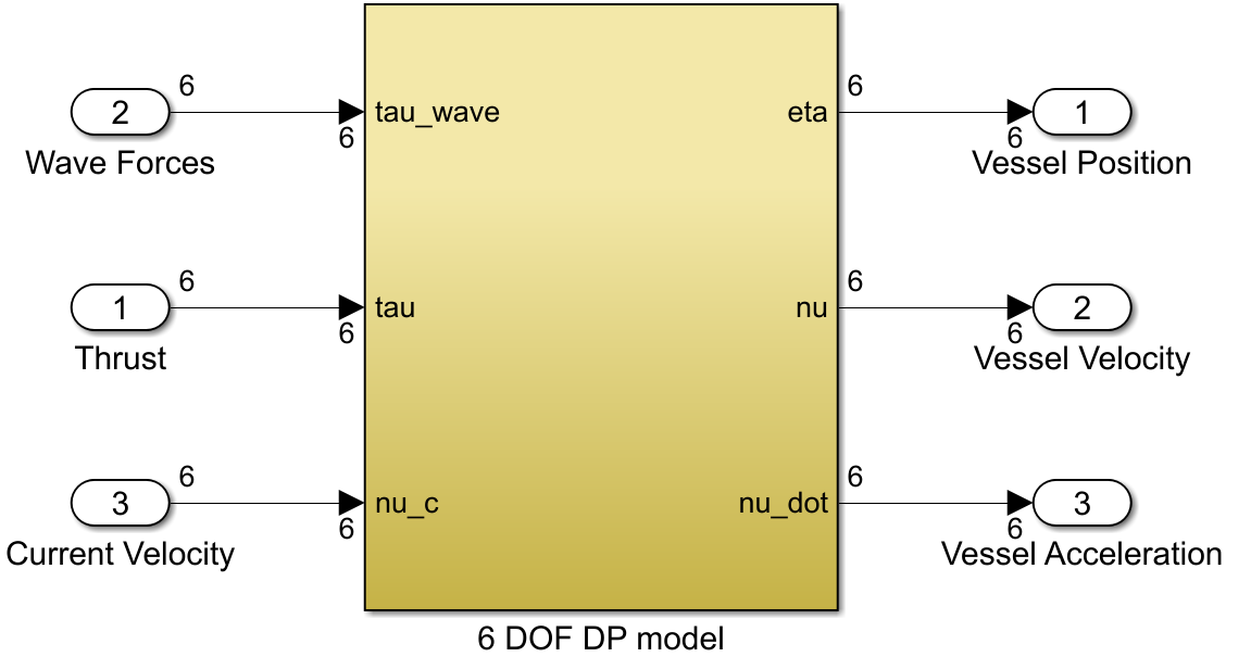
Table 19: Thruster Dynamics inputs and outputs (I/O).
| Name | I/O | Unit | Description |
|---|---|---|---|
Wave_Forces[1] | I | N | Wave force in surge |
Wave_Forces[2] | I | N | Wave force in sway |
Wave_Forces[3] | I | N | Wave force in heave |
Wave_Forces[4] | I | Nm | Wave force in roll |
Wave_Forces[5] | I | Nm | Wave force in pitch |
Wave_Forces[6] | I | Nm | Wave force in yaw |
Thrust[1] | I | N | Thrust force in surge |
Thrust[2] | I | N | Thrust force in sway |
Thrust[3] | I | N | Thrust force in heave |
Thrust[4] | I | Nm | Thrust moment in roll |
Thrust[5] | I | Nm | Thrust moment in pitch |
Thrust[6] | I | Nm | Thrust moment in yaw |
Current_Velocity[1] | I | m/s | Current velocity in surge |
Current_Velocity[2] | I | m/s | Current velocity in sway |
Current_Velocity[3] | I | m/s | Current velocity in heave (always zero) |
Current_Velocity[4] | I | rad/s | Current velocity in roll (always zero) |
Current_Velocity[5] | I | rad/s | Current velocity in pitch (always zero) |
Current_Velocity[6] | I | rad/s | Current velocity in yaw (always zero) |
Vessel_Position[1] | O | m | Vessel position in north |
Vessel_Position[2] | O | m | Vessel position in east |
Vessel_Position[3] | O | m | Vessel position in down |
Vessel_Position[4] | O | m | Vessel position in roll |
Vessel_Position[5] | O | m | Vessel position in pitch |
Vessel_Position[6] | O | m | Vessel position in yaw |
Vessel_Velocity[1] | O | m/s | Vessel velocity in surge |
Vessel_Velocity[2] | O | m/s | Vessel velocity in sway |
Vessel_Velocity[3] | O | m/s | Vessel velocity in heave |
Vessel_Velocity[4] | O | rad/s | Vessel velocity in roll |
Vessel_Velocity[5] | O | rad/s | Vessel velocity in pitch |
Vessel_Velocity[6] | O | rad/s | Vessel velocity in yaw |
Vessel_Acceleration[1] | O | m/s^2 | Vessel acceleration in surge |
Vessel_Acceleration[2] | O | m/s^2 | Vessel acceleration in sway |
Vessel_Acceleration[3] | O | m/s^2 | Vessel acceleration in heave |
Vessel_Acceleration[4] | O | rad/s^2 | Vessel acceleration in roll |
Vessel_Acceleration[5] | O | rad/s^2 | Vessel acceleration in pitch |
Vessel_Acceleration[6] | O | rad/s^2 | Vessel acceleration in yaw |
Table 20: Simulator Communication’s OSP-IS variable groups.
| Name | Comprised variables | Description |
|---|---|---|
thrust | Thrust[1], Thrust[2], Thrust[3], Thrust[4], Thrust[5], Thrust[6] | Total thruster forces in BODY |
wave_forces | Wave_Forces[1], Wave_Forces[2], Wave_Forces[3], Wave_Forces[4], Wave_Forces[5], Wave_Forces[6] | Total wave forces in BODY |
current_velocity | Current_Velocity[1], Current_Velocity[2], Current_Velocity[3], Current_Velocity[4], Current_Velocity[5], Current_Velocity[6] | Current velocity vector |
position_6dof | Vessel_Position[1], Vessel_Position[2], Vessel_Position[3], Vessel_Position[4], Vessel_Position[5], Vessel_Position[6] | Vessel position in NED frame |
position_3dof | Vessel_Position[1], Vessel_Position[2], Vessel_Position[6] | Vessel position in NED frame |
velocity_6dof | Vessel_Velocity[1], Vessel_Velocity[2], Vessel_Velocity[3], Vessel_Velocity[4], Vessel_Velocity[5], Vessel_Velocity[6] | Vessel velocity in BODY frame |
velocity_3dof | Vessel_Velocity[1], Vessel_Velocity[2], Vessel_Velocity[6] | Vessel velocity in BODY frame |
acceleration_6dof | Vessel_Acceleration[1], Vessel_Acceleration[2], Vessel_Acceleration[3], Vessel_Acceleration[4], Vessel_Acceleration[5], Vessel_Acceleration[6] | Vessel acceleration in BODY frame |
acceleration_3dof | Vessel_Acceleration[1], Vessel_Acceleration[2], Vessel_Acceleration[6] | Vessel velocity in BODY frame |